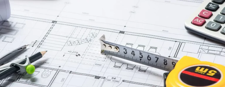
How to Estimate Mechanical Drawings Like a Pro
To Estimate Mechanical Drawings, you need to understand a plethora of information. This information will help you understand a mechanical drawing.
ESTIMATE MECHANICAL DRAWINGS LIKE A PRO!
A Mechanical Drawing Explained
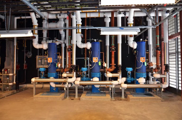
These drawings are technical drawings that use specialized tools to explain various mechanical systems. The systems are heating, ventilation, and air conditioning. One of the primary functions of these drawings is to convey all the essential information about a system’s designs and components.
Typically, a single mechanical drawing encompasses a range of elements. It can be symbols, texts, layouts, dimensions, and much more. All of this information will help in understanding an estimator in getting accurate estimates. But foremostly, an estimator must know these elements as well as how to Read Mechanical Drawings.
In the following discussion, we will be discussing these elements for you to have a better understanding of mechanical drawings. So, let’s get right to it!
What Methods are Used for Mechanical Drawings?
There are two common methods by which mechanical drawings are created. They are as follows:
Manual Method
In this method, estimators create mechanical drawings by hand. They use tools for drawing, such as pencils, rulers, protractors, and paper.
CAD Method
With the advent of computer-aided designs, manual drawings have become obsolete. The two subsidiaries of the CAD method are as follows:
Two-Dimensional CAD
Often known as AutoCAD, it is used for arcs, circles, curves, and straight lines.
Three-Dimensional CAD
This is the most advanced method for creating mechanical drawings. It primarily defines the geometrical aspects of a mechanical component from multiple views.
Now that you know about what methods are the most common methods for developing mechanical drawings. Let’s learn about what are the standard features of a mechanical drawing.
Standardized Features and Line Styles in a Mechanical Drawing
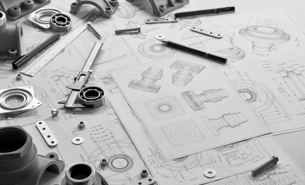
Geometrical Layout
It refers to the shape of a mechanical component from different perspectives. It explains a component’s appearance, as to how it will turn out.
Tolerances
How much variation exists in each dimension is known as tolerance. In other words, there is a difference between mechanical parts in an assembly line. Tolerance consists of an upper and a lower limit.
Dimensions
It is crucial to determine the size of a mechanical component. Estimators determine this by mentioning the tolerance of a mechanical part.
Furthermore, there are several line styles that are used in a mechanical drawing. The most commonly used line styles are:
- Continuous Lines
- Cutting Plane Lines
- Centre Lines
- Hidden Lines
- Extension and Dimensional Lines
- Broken View Lines
Now that you know about standard features and Line Styles of a mechanical drawing, let’s discuss various view types for a mechanical drawing.
Types of Views for a Mechanical Drawing
Basic view
Also known as multiple view, this is the most commonly used viewing. It covers front, top, and side views
Auxiliary view
The surfaces that are not compromised by any kind of distortions can be viewed by an auxiliary view.
Sectional view
This type of viewing is used by manufacturers or engineers to have a better look at the interior of mechanical components.
Exploded view
This view focuses on how various components in an assembly relate to each other.
So far, you have acquired the knowledge about what a mechanical drawing includes and how it’s made. Let’s explore how a mechanical drawing can be estimated.
How to Estimate Mechanical Drawings?
Estimating a mechanical drawing is a systematic approach to evaluate how many resources will be required and what their costs will be. Let’s break down the key steps that are taken to estimate a mechanical drawing:
Comprehend the Project’s Scope
First, you have to review the mechanical drawings and analyze the scope of a project. Once you have done that then identify all the components by breaking them down into assemblies. For this, you have to use theory dimensions, geometry, and tolerance.
Decide what you need and how much
In this step, you will quantify the required materials. For materials, you have to perform a material takeoff by reading the measurements given under the blueprint. These drawings will help you to accurately measure the area of a mechanical component.
Mechanical Estimating Services for Accurate Project Costing
Mechanical Estimating Services from SMA MEP Estimate can handle this entire process for you. Our estimators are competent and reliable, with years of extensive experience in cost management for mechanical systems. By working with SMA MEP Estimate, you’ll receive a precise list of all required materials along with their exact quantities, ensuring your project stays on budget and schedule.
Factor in Additional Costs
To make sure that you have a comprehensive estimate, also account for overhead and contingency costs.
Overhead costs are operational costs such as rents, utilities, etc. On the other hand, contingency costs are those that help you tackle any unforeseen issues.
ACCURATELY ESTIMATE A MECHANICAL DRAWING WITH THE ABOVE INSIGHT AND INFORMATIVE TIPS!
Final Thoughts
In summary, a mechanical drawing is an extensive document that holds a great deal of information. That is why to Estimate Mechanical Drawings accurately, you have to understand what goes into a mechanical drawing. This will not only help you to obtain precise estimates, but it also assures that you can get the best possible performance out of a mechanical system. Achieving this can be possible with the help of this article, as it discusses in detail what a mechanical drawing is, its features, and the steps that ensure accuracy in the estimates.