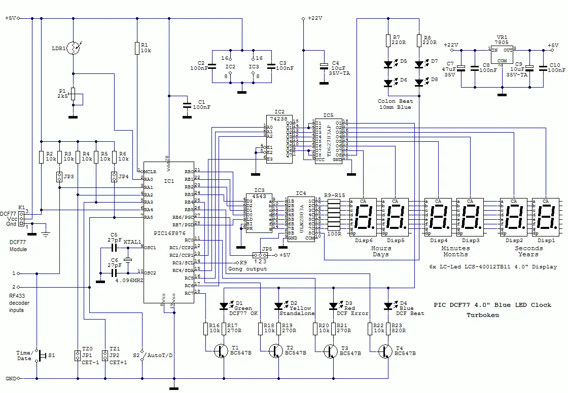
How to Read and Draw Basic Electronic Circuit Diagrams
Electronic Circuit Diagrams provide you with a detailed representation of circuits. These schematic drawings improve visualization and are critical for:
- Designing
- Troubleshooting
- Studying interconnection between electronic components
- Construction
Understanding the type of circuit is also essential for better functionality of an electronic circuit. It will help a great deal in drawing a specific circuit. The most common circuit types are as follows:
- Series Circuits
- Parallel Circuits
- Combination Circuits
It is important to Understand Circuit Diagrams, whether you are a fresher or an expert. These diagrams are the core of ensuring that one can proficiently conduct any work related to electrical systems.
LEARN WHAT IS INCLUDED IN AN ELECTRONIC CIRCUIT AND ELEVATE YOUR KNOWLEDGE ABOUT CATEGORISING VARIOUS CIRCUIT COMPONENTS EFFICIENTLY.
Brief Introduction of Electronic Circuit Diagrams
An Electronic Circuit Diagram is also called a schematic. It involves a graphical representation of a particular circuit. It uses internationally standardized symbols to represent different components in a circuit. These diagrams were used to design an electrical system in a project to install a new electrical system. To read a circuit diagram you need to familiarize yourself with various symbols and their roles in a circuit which are as follows:
1) Resistor
- Its symbol is a zigzag line or a rectangle depending upon the local standards.
- Its function is to maintain and restrict the flow of current in the Circuit
2) Diode
- A diode’s symbol is a triangle pointing towards a straight line.
- It is used to indicate in what direction the current is flowing. Its role is to make sure that the current is flowing in one direction
3) Capacitor
- It comprises two parallel lines one is a straight line and the other line is curved for polarized (negative and positive) capacitors.
- The function of a capacitor is the store and release Electrical energy as per requirement.
4) Inductor
- It encompasses several half-ring connections from one end to another.
- Its role is also to store Electrical energy but in a magnetic field when a current flows.
5) Integrated Circuit
- An integrated Circuit is a rectangle with markings or pins numbers to make it more specified.
- It has a variety of functions that are based on the internal circuits.
6) Switch
- In Electronic Circuit Diagrams, s switch is a line interruption in a straight line that is for providing a connection or a disconnection.
- Its role is to control the flow of current via opening or closing the connection
7) Power Source
- A power source is a long or short line or maybe a circle with positive and negative markings.
- It provides the necessary and required current to the Circuit.
All of these components must be accounted for while determining Electrical Estimating Services Cost. Thus, an estimator must make sure to consider these major components in the estimation process. Otherwise, an electrical system might not perform up to its full potential.
How to Read Electronic Circuit Diagrams
Following are the steps applied accurately and comprehensively in reading a Circuit diagram:
- The first step is to identify all the necessary components in a Circuit
- Second, you have to underhand adjust the flow of current so that it does not damage the capacitor
- Distinguish and divide into sub Circuits and interconnect them for better performance
- Track the flow of current from a signal input or output path
How to Draw Basic Electronic Circuit Diagrams
The second stage is how to draw a circuit diagram. Three areas are essential to understand in this stage which are as follows
- A Power source
- Circuit components
- A closed loop
In drawing Circuit Diagrams Following rules must be followed:
- Wiring and cable in a circuit must be drawn in a straight line without any Curves
- There must be no Curves and crossing among wires and cables otherwise it will disrupt the flow of current
- Correct and standardized symbols must be used for each component to understand functions better
- It is a must that there are no breaks in a complete circuit as a fully drawn circuit forms a closed loop from the starting point till the end
Electrical Estimating Services Florida calculates construction cost of electrical components by using advanced tools and software. There are several software’s which ensure accuracy in cost projections such as:
- Trimble
- ConEst
- McCormick Systems
- On Screen Takeoff
- Planswift
- Bluebeam
- Quest Estimating
- Stack
LEARN WHAT IS INCLUDED IN AN ELECTRONIC CIRCUIT AND ELEVATE YOUR KNOWLEDGE ABOUT CATEGORIZING VARIOUS CIRCUIT COMPONENTS EFFICIENTLY.
Final Verdict
In summary, drawing and reading Electronic Circuit Diagrams is a complex procedure. An expert must be knowledgeable about all the components involved in a circuit and what they do. This article discusses various components of a circuit and their roles. In addition to that, it also discusses a variety of circuits that are frequently used. This will allow a beginner to better understand how to read and draw a basic Circuit diagram.


